210
Elsewhere on this website we covered the process of adjusting
one TV camera.
Now we'll cover how to adjust an array of cameras so that their
brightness levels and colors match.
As before, you have to get each camera to work right to
begin with, performing all of the steps you did for the single
camera. Theoretically, if each camera were adjusted "right,"
they'd all match. Theoretically. In real life, a little more
massaging is necessary. Since studio cameras often shoot
different angles of the same scene, color and brightness
differences become quite noticeable. Studio cameras have to
match quite perfectly. Studio cameras, therefore, come with
separate camera control units (CCUs), bedecked with broods of
buttons and knobs for tweaking more enhancement and finesse to
the process. Studio cameras don't necessarily mean expensive
cameras. "Industrial" quality cameras, as well as ENG
cameras
with genlock inputs, are all studio-friendly and will behave as
described below.
Your cameras, of course, would be switched to the EXTERNAL
SYNC mode, and would be adjusted through their separate CCUs in
the engineering or control room. Besides iris, gain, and
pedestal controls (both auto and manual), there are red and blue
gain controls to adjust the redness and blueness of the picture.
R and B pedestal controls adjust the amount of redness and
blueness in the dark parts of the camera's picture.
A cable length control adjusts for the fact that some
cameras may have longer cables than others. A long cable weakens
the high frequencies in the signal, making the image fuzzier and
the colors weaker than its brothers. Adjusting this control to
match the actual cable length to the camera will compensate for
these evils.
H phase (or horizontal phase) is an adjustment that delays
the picture from one camera to make it match the timing of
another camera's picture. Cameras that aren't horizontally
phased will cause your TV image to glitch or jump left or right
every time the image is switched from one to the other.
Subcarrier phase or SC phase is like the hue control on
your TV set. It adjusts all the colors at once. Turned in one
direction, your reds will start to look a little orange. Turned
in the other, this knob now makes your reds look a little magenta
while affecting the green and blue at the same time. This camera
adjustment allows you to match the hues of one camera with those
of another.
The theory behind the action -
Before we begin, let's explore what it is we're trying to
do. In order to mix pictures through a switcher, be it a tiny
Toaster or a giant Grass Valley the size of a ping pong
table, the same is always true: the source signals must be
synchronized and their colors in phase. You can change partners
(pictures) in the middle of a dance only if all of you are in
step with the same music.
To do this, "house sync" is sent to each of the cameras
to
keep them in step. The cameras send their sync and pictures back
to the switcher to be combined. Some camera cables are longer
than others, delaying the signal. Some cameras get their genlock
or external sync secondhand, perhaps looped through another
camera, delaying the sync, thus delaying the output picture.
Some cameras process their signals more slowly than others. For
whatever the reason, the signals are unlikely to arrive at the
switcher exactly in step just by luck.
No big problem. One knobtwiddle of the H phase control
(Horizontal phase) brings the picture in line. Here's the part
that's hard to understand: Although the H phase adjustment
appears to delay or advance the picture and sync to line up with
other cameras, it doesn't. Pictures are too hard to store and
delay (expensive delay lines and TBCs do these jobs). Instead,
H
phase advances and retards sync (which is easy to do). The
camera spits out its picture depending on when it hears the sync
drumbeat, so moving the sync pulse to the "right" place
in time
delays or advances the camera's sync and picture output whatever
amount is needed to make it arrive at the switcher at the right
time.
Subcarrier is similar. Subcarrier is a high frequency
(3.58 MHz) signal added to your video signal. A sample of the
subcarrier is added to the back porch part of sync and is used
as
a reference against which to make comparisons. The subcarrier
reference is called burst. If you looked closely at one
vibration of a color video signal, you'd see the ripple of little
subcarrier vibrations riding along atop it. TV circuitry
compares these ripples with burst to see if they are in step with
burst, or maybe a little ahead or behind. If the ripples preceed
burst, the picture element may be interpreted as green. If the
ripples vibrate later than burst, the picture element may be red.
Thus subcarrier determines the colors in your picture.
Naturally, these ripples must arrive right on time to guarantee
accurate color. By adjusting the subcarrier phase control, you
advance or delay these ripples, moving all the colors (the hue)
of your picture.
What does this all look like on a TV screen, waveform
monitor, and vectorscope? Imagine you had three similar cameras
switched to bars and a "dumb" switcher (without blanking
processors --- explained shortly), sending the result to a TV,
waveform monitor, and vectorscope (switched to EXTernal sync).
Camera #1 is on. The sync pulse is centered on the waveform monitor.
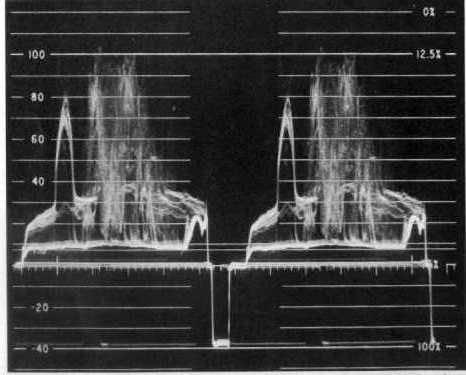
[FIG. 1 - Above is the waveform monitor display
showing the output of the switcher.
The sync pulse is in the center.
It shouldn't budge as you switch cameras.
The peaks are at 100 IRE where they should be.
The valleys drop down to 7.5 IRE as they should.
This example happens to be in the waveform monitor's IEEE mode
where the burst is removed from the sync pulse.]
[Fig. 2 - The above diagrams a sync pulse for a color picture.]
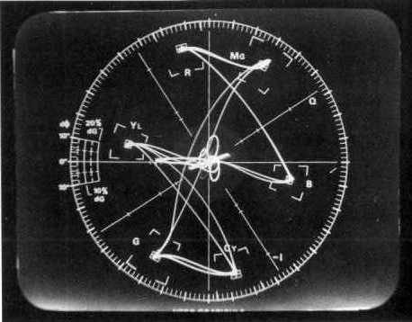
[Fig. 3 - Above is a vectorscope display of color bars.
Burst is the squiggle pointing straight to the left.]
Burst points to 9 o'clock on the vectorscope. The
picture on your TV monitor is stable and centered. Now switch
to
camera #2. Burst and sync should not move or change. If the sync
pulse
jumps to the left or right on the waveform monitor, then camera
#2 needs to have its horizontal phase advanced or delayed. If
burst and the dots representing color bars jump to another
position on your vectorscope, then your subcarrier phase is off.
On the TV monitor, you'll see the picture jump sideways and/or
change bar colors.
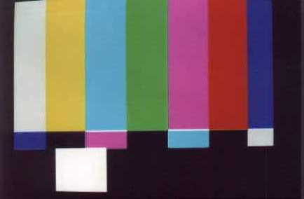
[Fig 4 - Above: The test signal "color bars" on a TV
monitor.]
To perform timing adjustments, you could switch back and
forth between cameras #1 and #2 while adjusting #2 until sync
stayed still, burst stayed at 9 o'clock, and bars stayed the
same color.
The above works with a "dumb" switcher, like the Toaster
without blanking processors, and expensive switchers with
blanking processor overrides. Most other switchers have blanking
processors that strip off the camera sync and replace it with
the
switcher's. This hides the evidence we were looking for; the
sync and burst won't jump like we expected it to. The sync will
stay rock solid, but the pictue will jump sideways if H phase
is
off. So a picture jump is what you watch for on your waveform
and TV monitor, and adjust to get rid of it.
Let's review: Camera #1 sends its sync and video to the
switcher and the switcher sends the image to a TV monitor and
to the waveform monitor and vectorscope. Thus you can see the
picture three different ways. You switch to camera #2 and if H
phase is off, the whole
works jumps left or right on your waveform and TV screens. The
blanking processor, if you have one, removes the camera sync and
inserts its own; thus sync doesn't jump. But the picture still
jumps. You use that to tell whether H phase is right.
Now you're ready for step-by-step camera adjustments.
Step 1 - Getting turned on -
Before trying to match your cameras' brightness and colors,
get everything warmed up.
a. Turn on the house sync generator
b. Turn on pulse distribution amplifiers if your system has them
c. Turn on the switcher
d. Turn on the camera control units and cameras
e. Turn on your TV monitors, waveform monitors, and vectorscopes
f. Let the system warm up for five minutes
Step 2 - Calibrate your monitors -
a. Send color bars to your TV monitor and calibrate it for
proper contrast and coloration.
b. Set your monitors (TV, waveform, and vectorscope) to EXTernal
sync, if possible. Calibrate them (or have a technician do so)
if they've seen a lot of service since last calibration. You
want them to tell you the truth.
Step 3 - Properly adjust each camera independently:
a. Normalize the switches on the camera (0 dB gain,
normal shutter speed, etc.)
b. Adjust the COLOR TEMPERATURE wheel.
c. Adjust the camera's IRIS or switch to AUTO IRIS.
d. WHITE BALANCE.
e. BLACK BALANCE.
f. Adjust CABLE LENGTH controls to match the camera.
g. Switch each camera to BARS and examine the dots on the
vectorscope. If some are weak (don't reach their
boxes) and some are too strong (overshoot their boxes),
the camera's encoder needs attention. If all are weak
or strong, try adjusting the CABLE LENGTH control some
to boost or cut the chroma gain.
h. If you're a perfectionist, patch each camera output
directly to the waveform monitor. Switch the waveform
monitor to H-MAG (magnifying the waveform of the
picture in the horizontal direction, as shown in Fig. 1). Aim
the camera
at a white card. Check that the test signal's video
begins 9.4 microseconds after the beginning of sync, as shown
in Fig. 2.
(Calibrating the waveform monitor so that you know how
many microseconds equal each tick on the scale is
beyond the scope of this article; have a technician do
this once for you.) This assures that the picture
starts just the right amount of time after sync ends.
i. Switch the camera to BARS and feed its signal to your
waveform monitor.
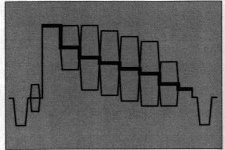
[Fig. 5 - Diagram of waveform monitor showing
color bars. Each of the boxes represents one of
the color bars. If the waveform monitor is switched
to IEE mode to show only the black & white parts
of the picture, you'll see only the thick stairsteps
seen here, and not the boxes. The above diagram will
probably be repeated twice on your waveform screen.]
Switch the waveform monitor's
RESPONSE control to IEEE so it "sees" only brightness,
not color (making the waveform easier to read). The
white bar should plateau at either 77 IRE (77% white)
or 100 IRE (100% white) and the darkest part of the
picture (called SETUP) should be at 7.5 IRE (TV black).
If necessary, adjust PEDESTAL to hit the 7.5 IRE mark
if it's off. Adjust GAIN to hit the 77 or 100 IRE
mark. Some bar generators make a 77% white bar and
others 100%. How do you tell which kind you've got?
Look at the stairsteps. If each step is equal (paying
particular attention to the two top steps), then the
white bar is 77 IRE. If the top step is about double
the others (about 12 IRE higher than the yellow step
which is 6 IRE higher than red and so on), then the
white bar is 100 IRE. Most bar signals work at 77 IRE.
Split field bars (like in Fig 4) work at 77 IRE but the white
box at
the bottom of the chart is 100%.
Step 4 - Timing the cameras to "the system" -
a. Switch the cameras to bars.
b. Switch your switcher to black.
c. Fade from black to camera #1. If perfect:
1. The dots on the vectorscope go straight from the center
toward their boxes during the fade, ending inside their
boxes.
2. The sync stays in the same place and doesn't pop
sideways at the very end of the fade.
3. The picture fades in and doesn't pop sideways at the
end of the fade.
If perfect, do the same with camera #2, etc. If not
perfect, do more work on camera #1.
1. Start with subcarrier phase adjustments because these may
affect H phase later.
a. Fade to black
b. Make sure burst is at 0 degrees (points to 9 o'clock)
c. Fade slowly up to camera #1 bars. Neither burst
nor colors should rotate. If they do, adjust SC
phase. Note that the switcher's blanking processor may
hold burst in the right place (hiding the truth) but
the bars will still change color (dots will rotate and
that's your tipoff that SC still needs a tweek. If a
tweek isn't enough, look for a 0/180 degree switch, throw
it, and tweek again. The switch is a gross adjustment,
SC phase a fine adjustment.
2. Now do H phase.
a. Fade to black
b. Fade slowly up to camera #1 bars while watching sync
and video on the waveform monitor.
c. When you reach the end of your fade, watch for the
picture to jump sideways. If it does, your H phase
needs a tweek. If you have no blanking processor in
your switcher, you may see two sync pulses and your
picture may tear, or you may see the sync pulse move.
Switchers with blanking processors hide this from you
and you only see the picture jump sideways near the end
of the fade.
3. Now that camera #1 is timed correctly, move on to camera #2,
etc.
Step 5 - Matching the cameras -
This step is easiest if all cameras are the same brand and
model; they will make their bars the same size and color.
Dissimilar cameras are difficult to match under any circumstances
because they tend to "see" differently. For example,
3-chip
cameras see colors a little differently than 1-chip cameras.
a. Make a horizontal split screen showing the bars from
camera #1 in the top half of the screen and the bars
from camera #2 in the bottom.
b. Make fine adjustments to camera #2's SC phase to make
its colors match camera #1. You can use your TV
monitor for this, or your vectorscope (the dots will
overlap when perfect).
c. Repeat the process comparing the other cameras to #1.
Remember that if the cameras are dissimilar, their bars may
be shaped differently and may not line up. The colors of the
bars, regardless of their exact position, should still match.
Step 6 - Matching the images (also known as "looking for
trouble") -
The color bar test described above matched the camera's encoders
and
subcarrier phase. This doesn't guarantee that the cameras would
"see" brightness and color exactly the same way; their
lenses,
aging electronics, and other variables conspire to make them each
see things a little differently.
a. Light and prepare the set for shooting.
b. Uncap the cameras, switch them off BARS and aim them at the
set. Make sure the set contains something white and something
black in it.
c. Switch to camera #1 and observe the results on your waveform
monitor. The white peaks should be at 100 IRE, the blackest
blacks at 7.5 IRE. If not, your lighting, iris, gain, or
pedestal could be causing a problem.
d. Repeat the process with the other cameras.
e. Now to color. Aim the cameras at the performer or a standin
(sometimes a color photo of a fair skinned model is used here).
f. Again, split the screens and look for variances in color and
brightness. Pick one camera as the "master" and tweak
the other
cameras to match it. Be aware that perfection isn't always
pretty. The lighting from two different angles may be different.
If your cameras are tweeked precisely the same, the shots from
the two angles will look different. It may be necessary to
adjust one slightly "wrong" to make it have the same
"look" as
another. Camera shading is an art flavored science.
Now all your cameras should look pretty close to the same.
There is a bit more to the process than this; that's why TV
stations hire engineers, and that's why the engineers always look
busy.
*********************
BOX 1 WHAT IF YOUR TV MONITOR, WAVEFORM MONITOR,
OR VECTORSCOPE HAVE ONLY INTERNAL SYNC?
Some computer board level waveform monitors and
vectorscopes don't have external sync inputs. How do these
effect your test procedure?
If your monitors are tuned to internal sync, and you
dissolve from one camera to another camera having an H Phase
misadjustment, sync may appear stable. If it shifts at the end
of the fade, it may self correct in the blink of an eye --- an
effect hard to notice. Your externally synced TV monitor will
show a normal picture that may shift horizontally at the end of
the fade --- an effect easier to see, so pay attention to your
TV
monitor.
If you dissolve from one camera to another having an SC
phase misadjustment, your externally synced vectorscope will show
the bars in the wrong place at first, then snap into the right
place at the end of the fade (as the vectorscope "locks on"
to
the signal). Your monitor will show the wrong color bars during
the fade, then at the end of the fade the bars will snap into
place (as the TV "locks on").
The advantage of external sync is that your monitors don't
"lock on" to the signal and make errant signals look
artifically
good.
| About the author | About Today's Video 4th. ed. | Return home |